Digital Headend System: CATV Headend Equipment
What a digital CATV headend contains: the receive, multiplex, CAS and QAM stages, the published rows that decide the order, and the chassis for each job. Each model named in this article is one of 190 in the Hanxing catalogue, published with its own specifications and datasheet.
Hanxing Team
Broadcast & IPTV Experts
The path this guide walks
- Feedssatellite, terrestrial and local sources arrive at the headend
- Receivetuners, demodulators or a gateway republish them as transport streams
- Multiplexselect the programs, remap PIDs, rebuild PSI/SI
- Scramble and insertCAS, SMS, EPG, OSD and advertising on the multiplex
- ModulateDVB-C QAM or DVB-T / ATSC / ISDB-T carrier on RF
- Distributecombine, amplify and feed the coax or a transmitter
A CATV headend ends in RF carriers on coax; the IPTV version of the same room ends in multicast streams instead.
A digital headend is the room where everything a site receives and everything it produces is turned into one line-up that every television in the building can tune. Cable operators call it a CATV headend; hotel, hospital and campus engineers call it the headend rack. The chassis are the same, and the order they sit in is the order the signal travels.
This guide walks that chain stage by stage — receive, process, scramble, modulate, distribute — and names the chassis in our catalogue that publishes each job. Every figure quoted below is printed on the product page of the model it belongs to. Where a page does not publish a value, this guide says so and sends you to the datasheet rather than estimating it, because a headend is bought on carrier count, PID capacity and output standard, and a guessed number only shows up at commissioning.
What Is a CATV Headend?
A CATV headend is the central equipment room of a cable or community television network: it receives satellite, terrestrial and locally generated feeds, converts them into transport streams, selects and scrambles the services viewers are entitled to, modulates those services onto RF carriers and injects them into the coaxial plant that reaches every outlet.
In an analog headend each channel was a separate carrier with its own processor; in a digital headend the transport stream is the unit of work, so selection, scrambling and re-labelling happen before the RF stage rather than at every channel.
That single change is what makes the modern room small. A digital headend can carry several hundred services in a handful of rack units because the services are compressed and multiplexed before they are modulated, and the modulator then places many services on each carrier instead of one.
The terminology around the room is worth fixing before the equipment list, because the three systems are frequently confused:
| System | What it distributes | Typical headend output | Receiving device |
|---|---|---|---|
| MATV | Terrestrial and satellite channels to one building | RF carriers on coax | The television's own tuner |
| SMATV | The same, from a private dish and antenna farm | RF carriers on coax | The television's own tuner |
| CATV | A cable network or a large private plant, with subscription control | QAM carriers plus conditional access | Cable set-top box or tuner |
| IPTV | Services to a data network | UDP / RTP multicast streams | Set-top box, smart TV app or hospitality TV |
A CATV headend is the subject here — the rack that ends in QAM carriers on coax. If the outlets are Ethernet and the receivers are set-top boxes or smart TVs, the room is an IPTV headend and the equipment list is different: the IP headend equipment guide covers that chain, and the section on choosing between the two is further down this page.
How Does the Signal Travel Through a Digital Headend?
Every digital headend, whatever its size, is the same eight stages in the same order, and each stage answers one question. If a quotation is hard to check, it is usually because two stages have been merged into one line or one box has been asked to do a job it does not publish.
The stages are:
- Receive — a tuner, demodulator or gateway locks the carriers the site is entitled to and republishes the services as transport streams.
- Encode — anything the site generates itself, from cameras to media players, is compressed into a transport stream.
- Multiplex — the wanted services are selected, unwanted PIDs dropped, PIDs remapped and PSI/SI tables rebuilt for the line-up.
- Scramble — where services are sold or restricted, the multiplex is encrypted to a conditional access standard.
- Insert — OSD, logo, advertising and EPG content are added to the transport stream so the receivers show what the operator wants them to show.
- Modulate — each output multiplex is placed on an RF carrier: DVB-C QAM for a cable plant, DVB-T, ATSC or ISDB-T for terrestrial distribution.
- Combine and amplify — carriers from all modulators are merged and set to a level the coax plant can carry.
- Distribute — coax to the outlet, or a transmitter where the coverage area extends beyond the building.
Two of those stages are optional in a given project — encoding only exists where the site has its own sources, and scrambling only where services are sold — but no stage can be skipped silently, because the receiver at the far end sees the result of the whole chain.
What Does a CATV Headend Diagram Show?
A CATV headend diagram is one line from the dish or antenna farm to the wall socket, and every block on it should carry a published row rather than an estimate. Six blocks carry the signal — receive, multiplex, insert, modulate, combine and outlet — and each is sized by a number printed on the model chosen for it.
Most drawings that circulate online are stencils from diagramming software or textbook figures of an analog plant, and neither tells a buyer what to specify. A drawing is worth keeping only if the tuner count, the carrier count and the output level on it can be checked against the datasheet of the chassis in the rack.
| Block on the drawing | Published row that fixes it |
|---|---|
| Feed — which satellites, terrestrial multiplexes and local sources arrive, and on which interface | Satellite tuners at "950~2150MHz" and cable tuning to "J.83A(DVB-C), J.83B, J.83C" on the FUQ4619C-3 |
| Receive — how many carriers are locked at once, and whether encrypted ones are cleared | Maximum PID remapping of "256 PIDs per input channel" on the FUQ3902B; "24 tuners inputs" on the FUQ4619C-3 |
| Multiplex — which services survive selection, and which PIDs carry them | "512" output PIDs over "0x0000—0x1FFF" on the FUQ4823C-2; "748 PID numbers for GE1" on the FUQ3504-2 |
| Insert — where EPG, OSD, logo and advertising join the stream | Model name publishes a "1-Channel Input DVB-ASI-IP" for the FUQ-OSD100; 2044 TS streams on the FUQ2044TL EPG system |
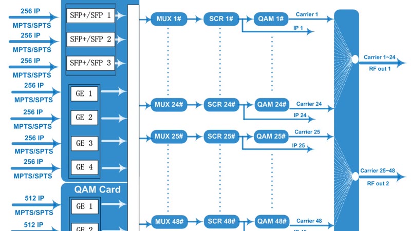
| Modulate — carrier count per output port, the standard, and the level it leaves at | "48 non-adjacent carrier" on the FUQ4459E, RF1 carrying 1~24 and RF2 carrying 25~48; 32 carriers on the FUQ4443-2 |
| Combine — where the carriers merge, and the level the plant receives | Output level published as "-20dBm~+10dBm(87~117dBµV), 0.1dB stepping" on the FUQ4459E; splitters and taps are the contractor's Bill of Materials |
| Outlet — which receiver, and therefore which standard, terminates the plant | DVB-C QAM or DVB-T COFDM carriers, so the screen's own tuner does the receiving |
The capacity arithmetic behind the carrier row is the part no drawing can show. In North American practice one 6 MHz slot carries one J.83B carrier, so an 860 MHz plant offers roughly 125 to 140 slots; in Europe the 8 MHz slot is the unit. A 256QAM carrier in a 6 MHz slot runs at 5.3605 Msps, about 43 Mbps on the wire and roughly 39 Mbps after the Reed-Solomon overhead, and a channel plan divides that figure by the bit rate of each service rather than guessing at it.
Three things stay off the drawing until the project is confirmed: the frequency plan, the carrier-to-service map and the level budget at each tap. The same block set is drawn for a satellite-only building in the SMATV system guide, and the chassis that do the modulating are listed on the modulator and modem page.
What Is on a CATV Headend Equipment List?
The table below is the equipment list in the order it sits in the rack, with the published example from our catalogue for each job and the line each example belongs to. Model names link to the page that carries the specification table for that exact unit.
| Stage | Job in the chain | Published examples |
|---|---|---|
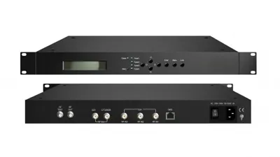
| Receive and turn-around | Lock satellite, terrestrial or cable carriers and republish the services as transport streams | FUQ3902B demodulator, FUQ4619C-3 tuner-to-IP gateway, FUQ41013K transmodulator |
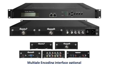
| Encoding | Compress HDMI, SDI, CVBS or IP sources into transport streams | FUQ4647B DTV processor, FUQ100 network encoder processor |
| Multiplexing | Select programs, remap PIDs, rebuild PSI/SI, merge feeds into one line-up | FUQ4823C-2 multiplexer scrambler, FUQ4218B TS re-multiplexer |
| Conditional access | Encrypt the services that are sold, through a CAS and an SMS | FUQ-1.0 conditional access system with SMS, FUQ-SMS subscriber management |
| Insertion and guide data | OSD, logo, advertising and EPG insertion into the multiplex | FUQ-OSD100 OSD insertion, FUQ-ADS advertising system, FUQ2044TL EPG system |
| Modulation | Place each output multiplex on an RF carrier | FUQ4459E 48-carrier QAM modulator, FUQ44105R-2 DVB-T modulator |
| ASI infrastructure | Switch, distribute, play and analyse transport streams at baseband | FUQ3515 ASI switcher, FUQ4713 ASI distributor |
| Transmission | Raise the signal to radiated power where coverage leaves the building | FUQ8322 DVB-T transmitter, FUQ8313 DVB-T transmitter |
The nine product lines those examples come from are listed on the IPTV and broadcast video encoder, HDMI and SDI encoder modulator, modulator and modem, IP gateway, multiplexer and scrambler, IRD, decoder and transcoder, transmitter and receiver, software and systems and other devices pages, and the whole range is on the product catalogue.
When Is a Modular Headend Processor the Right Frame?
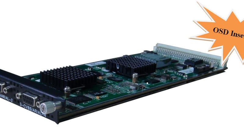
A modular headend processor is the smallest way to build a digital headend, because one 1U chassis takes the modules for several stages at once, and a site that needs two satellite services, four local channels and eight carriers buys one frame and the cards that match the job.
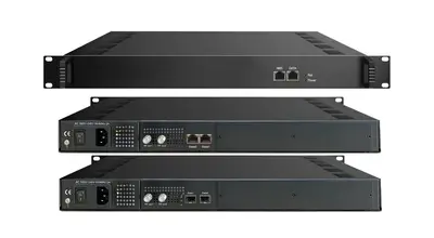
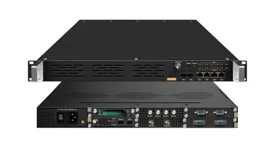
Our catalogue publishes four of those frames. The FUQ400B is published as a modular headend processor with six slots, the FUQ400 as a DTV head-end processor with six module slots, the FUQ300 as a six-slot modular headend processor with dual IP, and the FUQ230 as a modular headend processor with 128 IP inputs. Only the FUQ230 and the processor-modulator chassis publish a specification table; on the others the slot count and the module set are the published facts, and the datasheet for the exact configuration is the document to ask for.
Where the frame publishes its rows, they are the ones a designer checks. The FUQ230 page publishes a maximum PID remapping of "256 input per channel", "A/V PID Filtering" as its multiplexing function, and four modulation standards on the same chassis: DVB-C with "16 non-adjacent carriers output (maximum bandwidth 192MHz)", DVB-T to EN300744, ATSC A/53 and ISDB-T to ARIB STD-B31.
The FUQ4647B is the processor for sites that also have their own sources: published with 8 to 24 HDMI inputs, one ASI input and a USB port, encoding in HEVC/H.265 and MPEG-4 AVC/H.264 at "1Mbps~13 Mbps each channel" with "CBR/VBR" rate control, and a satellite tuner published at "950-2150MHz" with DVB-S2X demodulation from "0.5~45 Msps". A unit like that removes a separate encoder and a separate receiver from the rack, which is exactly why modular frames exist.
Which Receiver Locks the Feeds at the Headend?
The receive stage decides everything downstream, because whatever the tuners cannot lock can never reach the line-up. Two published figures matter here — how many carriers the box can lock at once, and whether it can clear the encryption on them — and both are printed per model.
For satellite feeds the FUQ3902B is the demodulator and descrambler of the range: published with DVB-S, DVB-S2 and DVB-S2X tuner inputs at "950-2150MHz", a maximum PID remapping of "256 PIDs per input channel", and the functions "PID remapping (automatically or manually), Accurate PCR adjusting, generate PSI/ SI table automatically" — the three jobs that turn a locked transponder into something the multiplexer behind it can use.
Where the headend must take a mix of standards, the tuner count is what decides the model. The FUQ4619C-3 tuner-to-IP gateway is published with "24 tuners inputs +2 ASI inputs +1 USB inputs", satellite tuners at "950~2150MHz", cable tuning to "J.83A(DVB-C), J.83B, J.83C", BISS descrambling at "Mode 1, Mode E" and "Web based management" for commissioning. The FUQ46610F publishes multi-mode tuners switchable across "60~890MHz" with "6/7/8 M bandwidth" alongside its satellite input at "950-2150MHz", and BISS descrambling of "Mode 1, Mode E (Up to 850Mbps)".
Where the building already runs coax and the televisions are the receivers, the receive stage is replaced by a transmodulator that re-modulates the satellite services onto DVB-C or DVB-T carriers inside the same chassis. That route has its own guide — the satellite transmodulator guide — and the DVB to IP gateway guide covers the opposite direction, from carrier to multicast stream.
Which Multiplexer and Scrambler Build the Line-Up?
The multiplexer is where the operator's intention becomes a transport stream: which services survive, which PIDs carry them, what the receiver sees when it scans. It is also the stage that carries conditional access, so the two are usually bought together as a multiplexer-scrambler.
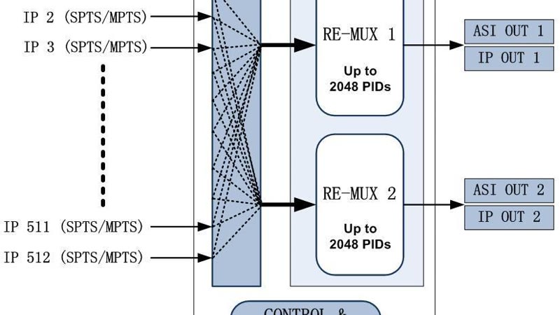
PID capacity is the first published row. The FUQ3504-2 IP multiplexer publishes "748 PID numbers for GE1", a packet format of "204/188 self-adaption for input, 204/188 is settable for output" and PID re-mapping among its functions. The FUQ3514 multiplexer scrambler publishes "512 per channel" as its maximum PID count alongside the scramble standards "ETR289, ETSI 101 197, ETSI 103 197" and "Local/remote connection", at a published consumption of "≤40W". The FUQ4823C-2 multiplexer scrambler publishes a "512" output PID count, an output range of "0x0000—0x1FFF" and full transparency — "Any PID transparent and mapping achievable".
Interfaces decide whether the chosen chassis fits the rack as built. The FUQ4218B TS re-multiplexer publishes "2 groups separate outputs (each group has 2 channels)" on ASI and "MPTS over UDP, RTP/RTSP output (RJ45), 1000Mbps Ethernet, DATA 1 and DATA 2" on IP, at a published weight of "3.5kg". The FUQ4214-2 IP multiplexer publishes "2 x independent channels of ASI output (each channel has 2 ports) (up to 210Mbps)" and "2 x IP (Unitcast/Multicast), UDP Protocol (up to 230Mbps)", with consumption below "25w" and a chassis of "482mmx410mmx44mm".
Scrambling is worth planning here rather than at the modulator, because the standard has to match the CAS in use. The FUQ4823D publishes its scramble standard as "ETR289, ETSI 101 197, ETSI 103 197" with the same dual ASI output groups and MPTS-over-IP output as its sibling, which makes the two interchangeable wherever the PID count allows. More on the business side of that decision is in the CAS and SMS headend guide, and the multiplexer selection itself is covered in the transport stream multiplexer guide.
Which QAM Modulator Fits the Carrier Plan?
The QAM modulator is the last processing box before the coax, and the carrier count it publishes is the number that sizes the whole headend. Modern units also multiplex and scramble internally, so one chassis often replaces a multiplexer, a scrambler and a rack of single-carrier modulators.
| Model | Published IP input | Published QAM carriers | Published PID row | Published MER |
|---|---|---|---|---|
| FUQ4459E | Max 1536 IP in through 3 GE ports, each up to 512 IP | 48 non-adjacent carriers, RF1 carrying 1~24 and RF2 carrying 25~48 | 512 per output channel | Not published on the page |
| FUQ4443-2 | Max 1024 IP input through 3 ports of 100/1000M | 32 carriers on one F port | 256 per channel | ≥ 40dB |
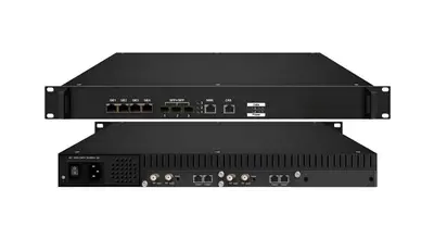
| FUQ4475 | Max 512 IP inputs from 6×100/1000M ports (4 RJ45, 2 SFP) | 64 non-adjacent carriers on two F ports | 256 per channel | ≥ 40dB |
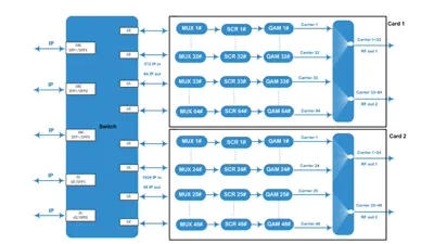
| FUQ200A | 10G SFP+/SFP input at up to 9600Mbps per port | 64 carriers per daughter card, RF1 carrying 1~32 and RF2 carrying 33~64 | 256 per output channel | ≥ 40dB |
| FUQ200B-2 | Max 256×4 IP through the GE ports and 256×3 through the SFP+ ports | 48 carriers per card, RF1 carrying 1~24 and RF2 carrying 25~48 | 256 per output channel | ≥ 40dB |
| FUQ4455B | 192 IP inputs over UDP/RTP | 4 carriers on one F port | 748 per input channel | Not published on the page |
| FUQ44105B-3 | 24 DVB-S2 tuner inputs plus 128 IP inputs and ASI | 16 RF carriers, published alongside 16 IP MPTS outputs | PID remapping, automatic or manual | ≥40db |
The two rows the table does not carry are the ones a commissioning engineer sets on site, and both are published per model. The output level of the FUQ4459E, FUQ4443-2, FUQ4475, FUQ200A and FUQ200B-2 is printed as "-20dBm~+10dBm(87~117dBµV), 0.1dB stepping"; the FUQ44105B-3 prints its own as "-20~+10dBm(87~107 dBµV), 0.1dB step". They are not the same range, which is why the level is read off the page of the model being specified rather than copied between pages, and why the RF output is set against the combiner the site actually uses.
Three rows repeat across the range and are worth knowing before the quotation. Modulation is published as "EN300 429/ITU-T J.83A/B/C" on the FUQ200B-2, the FUQ4443-2, the FUQ4475 and the FUQ4455B; constellations run "16, 32, 64, 128, 256QAM"; and forward error correction is published as "RS (204, 188)". Symbol rate is quoted on some models only — the FUQ4475 and the FUQ4455B print ranges of "5.0~7.0Msps, 1ksps stepping" and "5.0Msps~9.0Msps, 1ksps stepping" respectively, while the FUQ200B-2 publishes "3600~7000Ksps, 1ksps stepping".
For a single-channel job there is a simpler box: the FUQ4412B is published as a QAM modulator with one ASI input and an RF output in a "482mm×300mm×44mm" chassis drawing "22W". The full carrier-count picture, including the 112-channel and 128-channel processors, is on the modulator and modem page, and the general IP-to-QAM route is covered in the IP to QAM modulator guide.
When Should the Output Be DVB-T, ATSC or ISDB-T?
Where the site distributes over the air or through a private terrestrial plant rather than a cable system, the same line-up leaves through a COFDM or 8VSB modulator instead of a QAM one. The stages ahead of the modulator do not change; the standard and the carrier plan behind it do.
DVB-T is the most common of those outputs in this catalogue. The FUQ44105R-2 publishes the full COFDM set: standard "EN300 744", FFT "2K 4K 8K", constellation "QPSK, 16QAM, 64QAM", guard interval "1/4, 1/8, 1/16, 1/32", FEC "1/2, 2/3, 3/4, 5/6, 7/8" and an MER of "≥42 dB". The FUQ4415B publishes the bandwidths a channel plan needs — "DVB-T 6M, 7M, 8M" — together with a maximum PID remapping of "256 per input channel". Where the network is already DVB-T2, the FUQ3517X publishes both standards on one chassis, "DVB-(T) EN302 755" and "DVB-T EN300 744", over an RF range of "150~999MHz, 1Hz stepping", with an output level of "-15~+5 dBm, 0.1dB stepping", an MER of "> 43db" and a shoulder level of ">56dB".
The other two terrestrial standards are covered by dedicated models rather than by a firmware option. The FUQ4419BX publishes ATSC: modulation to "ATSC A/53", constellation "8VSB", bandwidth "6MHz", FEC "RS(208 188)+Trellis", "8 non-adjacent carriers" on one F port and an MER of "≥ 40dB". The FUQ4417K publishes ISDB-Tb: standard "ARIB STD-B31", "512 (or 1024)" input channels against "8 (or 16)" output channels, constellation "QPSK, 16QAM, 64QAM", guard interval "1/32, 1/16, 1/8, 1/4", transmission mode "2K, 4K, 8K", an MER of "≥40dB" and an ACLR of "-50 dBc". The FUQ3516R adds the hierarchy and interlacing rows ISDB-T receivers care about, published as "AIA+BIA+B+C" and three time-domain interlacing modes over a "6MHz" bandwidth.
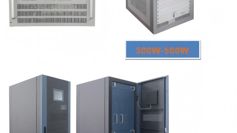
Behind the modulator, the transmitter decides coverage. The FUQ8322 publishes its output rating as "200W/300W/400W/500W/600 W Optional" across "470MHz~806MHz", with "support 4/16/32/64 QAM mode", a frequency accuracy of "MFN: ≤±100Hz / SFNI≤±1Hz", an MER of "≥36dB" and an output power variation of "±0.2dB". The FUQ8313 publishes a "1-5/8" output interface, an MER of "≥33dB", a shoulder level of "≥36dB@central freqnencyIF±4.2MHz" and out-of-band suppression of "≥65dBc" in a cabinet of "850mm×600mm×1695mm", with an LCD monitor on the front door. The smaller FUQ8351 publishes a TV standard row of "DVB-T/ATSC/ISDB-T" with a "4/16/32/64 QAM" modulating mode, which makes it the model to ask about when one modest coverage area has to be served from the headend room.
Terrestrial planning has its own guide — the DVB-T transmitter guide covers power, channel and coverage, the DVB-C, DVB-T and ATSC modulator guide compares the standards, and the ISDB-T modulator guide covers the Brazilian and LatAm case. The transmitters themselves are listed on the transmitter and receiver page.
Do You Need CAS, SMS and EPG in a CATV Headend?
A headend that sells subscriptions needs two pieces of software that never touch RF: a conditional access system to encrypt the services and a subscriber management system to decide who may watch them. Both are published in this catalogue as complete systems rather than as add-ons to a chassis.
The FUQ-1.0 conditional access system is published as an integrated CAS and SMS for digital television content, and the FUQ-SMS system is published as a subscriber management platform with million-level capacity — the scale figure that separates an operator's platform from a property's front desk. Because these pages publish the system and its role rather than a specification table, the interface list, the number of CAS simulcrypts and the integration path are datasheet questions, and they are the first things to confirm against the middleware already installed.
The same stage carries the data a viewer sees on screen. The FUQ2044TL is published as an EPG system, DVB-compliant, handling 2044 TS streams with ASI and IP output; the FUQ-OSD100 is published as an OSD and logo insertion device with one channel input on DVB-ASI or IP; and the FUQ-ADS is published as an advertising system, DVB-compliant, in a 1RU rack-mount unit with ASI and IP interfaces. Those three rows are what an operator compares when the requirement is "the receiver must show our logo, our channel numbers and our guide" rather than "the receiver must show the channels": all of it is inserted into the transport stream ahead of the modulator, so it survives whatever standard the headend outputs. The software and systems line is listed on the software and systems page and the insertion hardware on the other devices page.
The ASI infrastructure that follows is covered in the SDI to ASI headend guide, and the encode stage that feeds the line-up in the IPTV encoder guide.
Where Does ASI Still Belong in a CATV Headend?
Not every headend distributes ASI, but almost every headend uses it somewhere: as a backup path when the IP network is being worked on, as the link between a playout server and a multiplexer, or as the feed a technician taps when a service will not appear. The units that make that possible are simple and published one by one.
The FUQ3515 is published as an ASI TS switcher with "3 ASI Inputs 2 ASI Outputs" in "188 TS Packet Format" on BNC connectors, drawing "15W". The FUQ4713 is published as a DVB-ASI distributor with two inputs and twenty-four outputs, an LCD display and SNMP/NMS control, which is the unit that turns one headend stream into feeds for several racks. For offline material there is the FUQ-XQR professional TS player, published as a USB 2.0 input device with a DVB-ASI BNC output, and for fault finding the FUQXB transport stream analyzer, published with one ASI and one RF DVB-C input over USB 2.0 with real-time analysis up to 160Mb.
CATV Headend or IPTV Headend: Which One Does the Site Need?
The deciding question is what sits behind the wall and what sits at the end of it. If the outlets are coax and the receivers are televisions or cable set-top boxes, the headend ends in modulators; if the outlets are Ethernet and the receivers are set-top boxes running middleware, it ends in multicast streams.
| What the site has | What the headend should output | Where the cost sits |
|---|---|---|
| Coax to every room, televisions with DVB-C or DVB-T tuners | QAM or COFDM carriers from modulators | In the RF stage; no change to the wiring or the screens |
| Coax in part of the site, new data cabling elsewhere | Both: modulated carriers for the coax wing and multicast for the IP wing | In the headend; the two outputs share the same line-up |
| Cat6 everywhere, hospitality TVs or set-top boxes | UDP/RTP multicast to the network | In the network and the middleware, not in modulators |
| A cable plant with paying subscribers | QAM carriers plus conditional access and SMS | In the CAS and SMS integration |
Many projects end up needing both, because a property adds an IP wing while the older block keeps its coax, and the two outputs then share the same line-up. The practical test is the receiver list. Every television and every set-top box in the estate has to be written down with the standard it can tune before the headend is specified, because a DVB-C set-top box cannot see a DVB-T carrier no matter how good the multiplexer is, and a smart TV with no middleware cannot see a multicast stream without one. The hotel IPTV headend guide and the hospital IPTV system guide work through the site side of that list, and the IP headend equipment guide covers the IP-only version of this rack.
How Big Is a Headend Rack, and How Is It Laid Out?
The order inside the rack follows the signal rather than the supplier's convenience, and in this range almost every processing chassis is 1U, so a small headend is one 19-inch rack with units left over. The position that matters most is the modulator group: its F ports feed the combiner standing above the rack.
| Position in the rack | Published row |
|---|---|
| Top — the RF stage: QAM or COFDM modulators, dual F ports facing the combiner | "48 non-adjacent carrier" on the FUQ4459E, RF1 1~24 out and RF2 25~48 out |
| Middle — multiplexers, scramblers and insertion units on the ASI or IP core | "512" output PIDs over "0x0000—0x1FFF" on the FUQ4823C-2 |
| Middle — receivers and gateways, on the IF runs from the dish | "24 tuners inputs" on the FUQ4619C-3, alongside its 2 ASI and 1 USB input |
| Bottom — ASI distribution and patch, where a technician taps a feed | Two inputs and twenty-four outputs on the FUQ4713 |
| Spare — free units for a second carrier chassis or a backup path | 1U per chassis, "420mm×440mm ×44.5mm (WxLxH)" on the FUQ4459E |
The document that settles all of it before delivery is the equipment schedule: one line per unit, carrying a tag, the job it performs, the model, its rack position, its published consumption and its ports. Read that way, the table above is the schedule's answer sheet rather than a brochure.
Once the carriers and the interfaces are fixed, the physical rows decide whether the equipment fits the room. In this range almost every 1U processing chassis is published at the same width and depth, which is what makes a rack plan predictable before the quotation is finalised.
| Row | Published examples |
|---|---|
| Chassis, dense modulators | "420mm×440mm ×44.5mm (WxLxH)" on the FUQ4459E and the FUQ4475, and the same 1U footprint published as "420mm×440mm×44.5 mm" on the FUQ200A, the FUQ200B-2 and the FUQ4443-2 |
| Chassis, multiplexers | "482mm×300mm×44mm (WxLxH)" on the FUQ4823C-2 and the FUQ3504-2 |
| Chassis, receivers | "482mm×328mm ×44mm" on the FUQ3902B |
| Weight | "3.5kg" on the FUQ4218B and the multiplexer chassis, "5kg" on the FUQ200B-2, "3kg" on the FUQ4459E, "2.0kg" on the FUQ4214-2 |
| Consumption | "15.4W" on the FUQ4459E and the FUQ200B-2, "22W" on the FUQ4412B, "≤40W" on the FUQ3514, "50W(1 daughter QAM card)/75W(2 daughter QAM cards)" on the FUQ200A |
| Environment | "0~45℃ (operation), -20~80℃ (storage)" published on the modulator and multiplexer chassis that carry an environment row |
| Power | "AC 100V±10%, 50/60Hz or AC 220V±10%, 50/60Hz" on the FUQ4459E and the FUQ4443-2, and "AC 110V±10%, 50/60Hz Or AC 220V±10%, 50/60Hz" on the FUQ4823C-2 |
The transmitters are a different class of equipment and are planned as plant rather than as rack units. The FUQ8313 publishes a working temperature range of "-20~+50℃" against the headend's "0~45℃ (operation)", a cabinet of "850mm×600mm×1695mm" and a power supply of "AC, 220V±10%/50Hz", while the FUQ8322 publishes its supply as "AC, 220±20%, 50Hz AC, 380±20%, 50Hz" with cooling by an internal fan and a relative humidity limit of "≤95% (25℃ no condensation)". Those rows belong in the room design, not in the rack order.
What Drives the Cost of a CATV Headend?
A CATV headend has no list price, because the price is the configuration: the carrier count, the tuner count, the output standard and the software set the bill before the rack and the power supply do. Two projects for similar sites can differ by several chassis, and the difference sits in the RF stage rather than in the receivers.
Four rows move the price most, and each is a published row rather than a judgement call:
- Carriers. The RF stage is bought per carrier: 4 carriers on the FUQ4455B, 32 on the FUQ4443-2, 48 on the FUQ4459E and 64 on the FUQ4475. Doubling a line-up usually means a second chassis rather than a larger one.
- Tuners. Every transponder that has to be locked is a tuner, from a single tuner input on a transmodulator card up to "24 tuners inputs" on the FUQ4619C-3; satellite-heavy projects pay here instead of in the modulator.
- Scrambling and software. A free-to-air line-up needs nothing beyond the mux, while a pay line-up adds a scrambler, a conditional access system and subscriber management, plus the integration work that goes with them.
- Redundancy and insertion. A backup path, an EPG server and OSD or advertising insertion are each a unit in the rack, quoted per unit rather than as a percentage of the bill.
We build in our own Guangzhou factory and quote factory-direct against the configuration; standard chassis are quoted per unit, and OEM or ODM minimum quantities and schedules are confirmed against the model rather than published in advance. The modulator and modem page carries the carrier counts the RF stage is priced from.
What to Send Us for a Headend Quotation
A headend quotation is only checkable if the enquiry carries the list of receivers and the list of sources, so send those first and the model match follows from them. We do not publish list prices; every quotation is put together against the configuration you confirm.
The list that makes a fast quotation:
- The destination country and the site type — cable operator, hotel, hospital, campus, community plant.
- The sources: which satellites or transponders, which terrestrial multiplexes, which local HDMI, SDI or CVBS feeds.
- The receiver list: how many screens, and for each group the standard it can tune and whether it needs a set-top box.
- Whether services are sold or restricted, so the CAS and SMS route is settled before the scrambler is chosen.
- The carrier plan the plant can carry: how many QAM or COFDM carriers, which bandwidth, and the output level the combiner expects.
- The rack space and power available, and whether the site needs a transmitter as well as a headend.
Send that list and we return the model confirmation with the datasheet for each exact model and a quotation. Every unit is built in our Guangzhou factory, runs a 72-hour burn-in before dispatch, and we ship to 200+ countries. The fastest route is the contact form, and the FAQ answers the commercial questions first.
Frequently Asked Questions
What is a CATV headend?
A CATV headend is the equipment room where a cable or community television network receives its feeds, converts them into transport streams, selects and scrambles the services viewers are entitled to, and modulates them onto RF carriers for the coaxial plant. In a digital headend the transport stream is the unit of work, so selection and re-labelling happen before the RF stage rather than at every single channel.
What equipment does a digital headend need?
Eight stages in order: reception through tuners, demodulators or gateways such as the FUQ3902B; encoding where the site has its own sources, as the FUQ4647B does; multiplexing and scrambling, published on the FUQ4823C and FUQ3514; a conditional access system and an SMS; EPG, OSD and advertising insertion; modulation on a QAM or COFDM chassis such as the FUQ4459E; ASI switching and distribution; and a transmitter where coverage leaves the building.
How many QAM carriers can one headend chassis produce?
It follows the published carrier count of the model rather than the chassis size. Our range publishes 4 carriers on the FUQ4455B, 32 on the FUQ4443, 48 on the FUQ4459E and 64 on the FUQ4475, and the FUQ200 family is published as 96 QAM outputs on the FUQ200B and up to 128 DVB-C carriers on the FUQ200A in the same 1U frame.
Do I need a modulator with scrambling built in?
Only where the services are sold or restricted, and then the standard has to match the conditional access system in use. Scrambling to ETR289, ETSI 101 197 and ETSI 103 197 is published on modulator and multiplexer-scrambler pages in this range, including the FUQ4459E, the FUQ4443 and the FUQ4823D, with local or remote connection. Free-to-air line-ups need no scrambling at all.
Can one headend feed coax televisions and IP devices at once?
Yes, where the chassis publishes both outputs. The FUQ200B prints 48 IP output over UDP/RTP/RTSP per daughter card alongside its 48 carriers, and the FUQ200A prints 64 IP output over UDP/RTP/RTSP per card, so the same prepared line-up can leave as RF for the coax wing and as multicast for screens on the data network.
What is the difference between CATV, MATV and SMATV?
All three distribute television over coax, and the difference is what sits behind the wall and what the viewer pays for. MATV and SMATV carry terrestrial and satellite channels to one building or complex with no subscription control, while a CATV headend adds conditional access and subscriber management because the services are sold. A headend that ends in IP multicast instead of RF is an IPTV headend.
Do you supply the datasheet and a factory-direct quotation?
Yes. Send the site type and destination country, the sources, the receiver list with the standard each group can tune, whether services are restricted, the carrier plan the plant can carry, and the rack space and power available, and we return the model confirmation with the datasheet for that exact model and a quotation. Every unit is built in our Guangzhou factory, runs a 72-hour burn-in before dispatch, and we ship to 200+ countries.
What should be on a CATV headend diagram?
Six blocks, each carrying the published row that sizes it: the feeds and their interfaces, the receive stage with its tuner count and PID remapping, the multiplex with its output PID range, the insertion point for EPG, OSD and advertising, the modulator group with its carrier count and output level, and the combiner and outlet layer that hands the signal to the receiver.
How much does a CATV headend cost?
There is no list price, because the cost follows the configuration: carrier count, tuner count, output standard, scrambling and the software set. A free-to-air line-up of a few carriers is one 1U modulator with a multiplexer; a pay line-up adds a scrambler, a conditional access system and subscriber management. Send the carrier plan and the receiver list and the configuration is quoted factory-direct.
If the headend is part of a bigger project, the IP headend equipment guide maps the IP-only version of the same rack, the headend installation checklist covers rack, cabling and commissioning, and the CAS and SMS guide takes the software side further. The nine product lines are listed on the product catalogue, and the solutions pages show the chains end to end. Tell us the sources, the receiver list and the carrier count and we will match the chassis and quote it — the fastest route is the contact form, and the FAQ answers the commercial questions first.
Previous
SDI to ASI and QAM: Headend Signal Paths
Next
Satellite Transmodulator: DVB-S2 to DVB-C/DVB-T
Talk to the headend engineers before you specify
Send the model number you are looking at — or the channel count and the input and output formats you work with — and we answer with the datasheet, the configuration and a written price. The reply comes from the headend team in Guangzhou, not a sales line.